Recently updated on July 17th, 2024 at
CNC programming sounds difficult like a killer phrase for non-skilled operators because of many codes and enigmatic rules. However, once you understand the rules, it is not so hard to understand.
1.What is CNC programming?
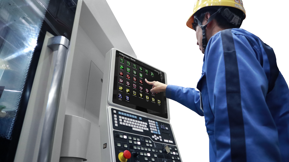
CNC stands for Computerized Numerical Control and a CNC machine is a machine computerized and numerically controlled. When we work on a material on the CNC machine, we use G-code and M-code for programming.
Programing codes are developed by several CNC controller manufactures such as FANUC, Siemens, Heidenhain and their systems are divided into lathe system and machining system. All of the manufactures use G-code and M-code so you might misunderstand that the string of the written programs means same command and order, but actually the command could be different even though they use same codes. Therefore, you need to be sure which CNC controller does a machine in use equip with before you start writing a program.
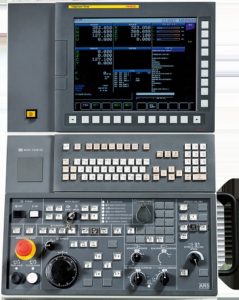
Since Nakamura’s machines equip the FANUC controller, we explain about how to activate a program in an easy-to-understand manner using FANUC CNC programming codes as an example in this column.
2.G-code and M-code
Firstly, you need to know about the language. CNC programming is composed of languages called G-code and M-code. Elementally, basic codes are present in two digits from 00 to 99, but depending on the configuration of a machine, we may use up to three digits.
2-1.G-code
As preparatory function, we mainly use G-code in manufacturing command, representing in numbers following sign G.
G-code has two types: one-shot codes (also called “non-modal”) that are valid only once, and modal codes that remain valid until another code in a same group is in execution. Don’t worry. There is no need to be panic about the groups. This grouping is aimed to avoid from interfering each command.
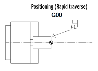
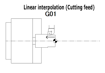
For example, if you state “G00: Positioning”, you cannot write “G01: Cutting feed” in a same line because a machine cannot follow both commands at the same time. Same as this condition, you cannot state “G02: Circular interpolation in clockwise” and “G03: Circular interpolation in counter clockwise” in a line because the machine cannot execute them simultaneously. Hence, these opposing codes are enclosed within one group to prevent from canceling commands each other.
The basic G-codes are about 70 in number from G00 to G99, but we do not usually use them all every time. Only if you remember frequently used codes, you can write a program.
Here are the often-used 16 G-codes that you’d better remember.
G-code selection
G00 Positioning (Rapid traverse)
G01 Linear interpolation (Cutting feed)
G02 Circular interpolation CW
G03 Circular interpolation CCW
G04 Dwell
G28 Automatic return to reference point
G40 Tool nose radius compensation cancel
G41 Tool nose radius compensation left
G42 Tool nose radius compensation right
G50 Coordinate system setting/Max. spindle speed setting
G54 Workpiece coordinate system 1 selection
G92 Thread cutting cycle
G96 Constant surface speed control
G97 Constant surface speed control cancel
G98 Per minute feed
G99 Per revolution feed
You can write G-codes in a same line if each code belongs to different groups.
2-2.M-code
M-code is miscellaneous function that we use in auxiliary command, calling for vary machine action. They are represented in numbers following sing M.
For example, M03 is a command for “Spindle start in forward direction”, and M08 is for “Coolant start”. Since the purpose of M-code is to activate a machine, machine builders rules the programming codes rather than CNC controller manufactures. Therefore, the codes called for action vary from machine builder to builder.
Imagine if you already had a machine produced by Builder A, then you purchased a new machine from Builder B. Both machines adopted FANUC controllers so you tried the same M-code digits used for the old machine to the new machine to state the same commands, but you came across to failure. This was because even though the M-code digits were same, the commands in execution were different. In this way, the machine builders customise the commands for their own machines respectively.
There are about 80 M-codes designated from M00 to M99 fundamentally, but same as G-code, you do not need to use them all.
Let’s take a look at the often-used 22 M-codes with Nakamura machines. Please note that those M-codes are not compatible to other builder’s machines and we customize them only for Nakamura machines.
M-code selection
M00 Program stop
M01 Optional stop
M03 Spindle start (forward direction)
M04 Spindle start (reverse direction)
M05 Spindle stop
M08 Coolant start (high pressure coolant)
M09 Coolant stop (low/high pressure coolant)
M10 Chuck close
M11 Chuck open
M20 Fixed air blow ON
M23 Chamfering ON
M24 Chamfering OFF
M30 Memory mode operation reset & restart
M41 Spindle selection (C-axis OFF)
M86 Spindle lock ON
M87 Spindle lock OFF
M88 Rotary tool spindle start (forward direction)
M89 Rotary tool spindle start (reverse direction)
M90 Rotary tool spindle stop
M91 C-axis selection (C-axis connection)
M98 Sub-program call
M99 End of sub program
As you see, there are about 80 M-codes but minimally required are about 22.
Please note that you can not state multiple M-codes per line but only one instead.
3.Coordinate system (Machine zero and Workpiece zero)
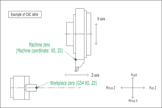
Secondly, we explain you about the coordinate system. CNC lathe has two zero points. One is machine zero which is the standard for the machine, and the other is workpiece zero where users creating a program can freely decide.

In a programming process, defining the workpiece zero point is important. Normally, we set the workpiece zero to the point where the machining end face and the center of a spindle intersect. The position of the workpiece zero is represented by coordinates of X0 and Z0. For X-axis, set the distance between the edge of a cutting tool and the center of a spindle to the shape correction, and for Z-axis, set the distance between the machine zero and the tip of a cutting tool to the shape correction. Since it is common to set the machining end face as Z0, a cutting tool moves toward minus direction when the machine cuts a workpiece chucked on the main spindle.
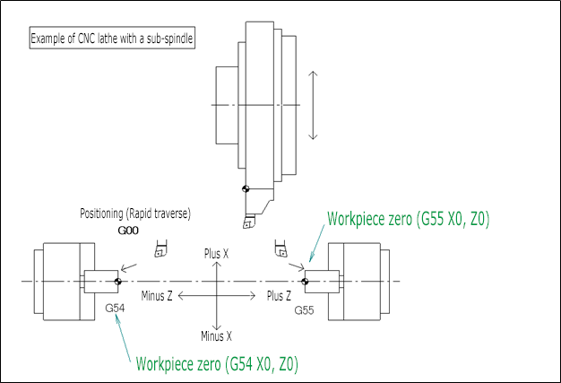
For machining on the sub-spindle, set G-code “G55: Workpiece coordinate system 2 selection” and calculate its coordinate based on it. The concept of the direction that the cutting tool moves is same as it is working with the main spindle: minus direction and plus direction. Therefore, when the machine works on the sub-spindle and the cutting tool moves in Z-axis, it moves toward plus direction.
4.Summary
As you see, you do not have to be afraid of programming. There is no need to remember all G-codes and M-codes. More importantly is understanding what the workpiece zero because if you set this point wrongly, you will ruin all the programing you made as a result. It is good to mark the workpiece zero on your drawing before starting programming. CNC programming will work out in good shape when the intention of the user is conveyed to the machine correctly in the end.
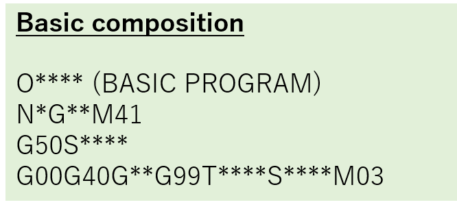
In the next column, we will discuss about the basic composition of a CNC program, absolute coordinates vs relative coordinates, and coordinate calculation.
Contact
If you have any inquiries about Nakamura-Tome’s machines or its CNC programming, please feel free to contact us.
You can also reach out our overseas presence or distributers in your area.
We deliver additional information and updates through social networking.
Please follow us on Facebook, Twitter or LinkedIn.