
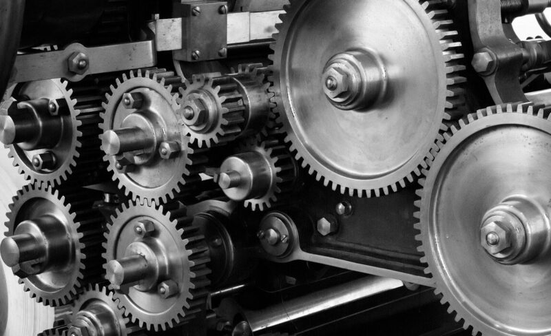
1.WHAT IS A GEAR?
A gear is a circular or cylindrical component with teeth along its outer edge. Gears work by meshing together to transmit, modify, or adjust power from motors or other driving forces. Among gears, smaller ones or the smallest in a set of two or more are called “pinions.”
Gears need to meet the following key requirements:
- Precision: Teeth must be accurately shaped to ensure smooth operation and to avoid premature wear.
- Durability: Gears are moving parts, so failure can stop the machine from functioning.
- Compactness and lightness: Particularly in vehicles and aircraft, gears must be small and lightweight, yet durable.
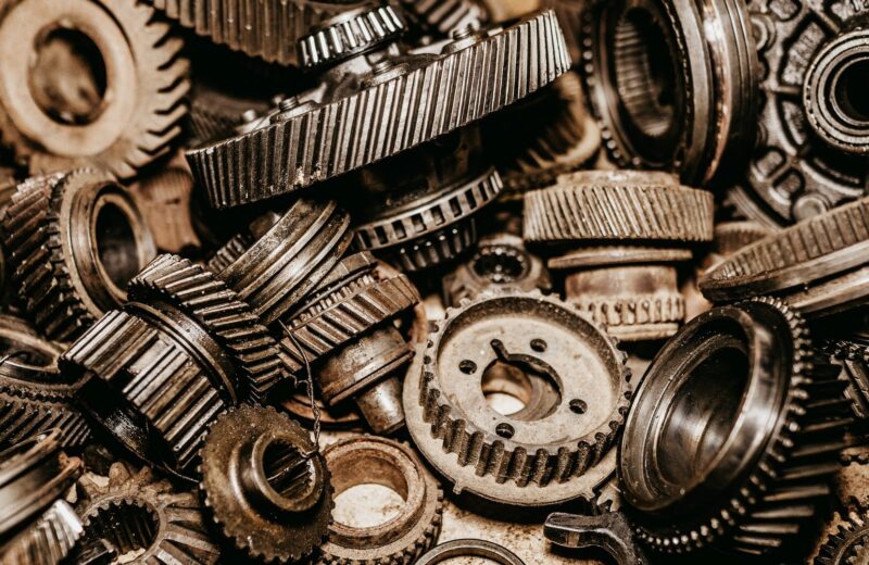
2. GEAR TYPES
Gears come in various shapes and designs based on their intended use.
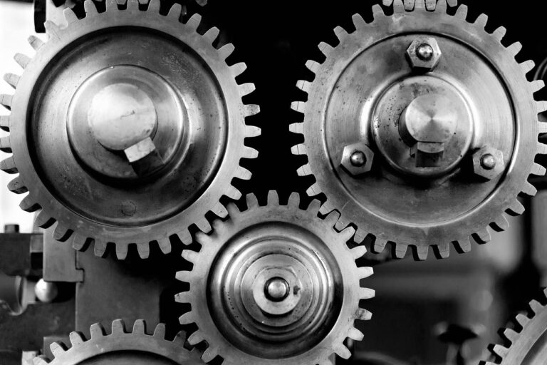
Spur Gears
The most common and standard gear type, simple to manufacture and widely used.
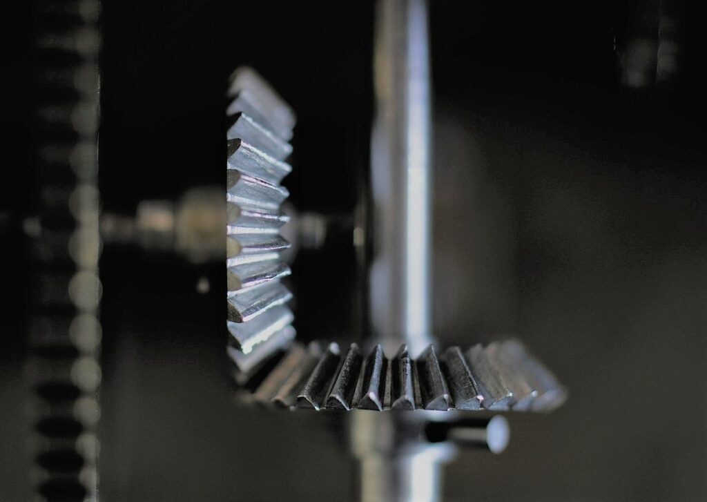
Bevel Gears
These gears are cone-shaped and used to change the direction of force between perpendicular axes (typically around 90 degrees). They can be further categorized into straight, helical, and spiral bevel gears based on their tooth shape.
Helical Gears and Double Helical Gears
These gears have angled teeth, which allow more teeth to engage simultaneously, increasing strength and reducing noise and vibration. However, they generate thrust force that requires specialized bearings. Double helical gears combine two helical gears to cancel out these thrust forces.
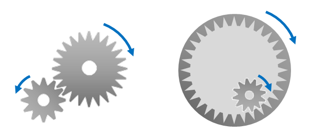
Internal Gear
An internal gear is a type of spur gear with teeth on its inner diameter. A notable characteristic is that while the rotation direction is reversed when two external gears are paired, a combination of an internal gear and an external gear results in the same rotational direction.
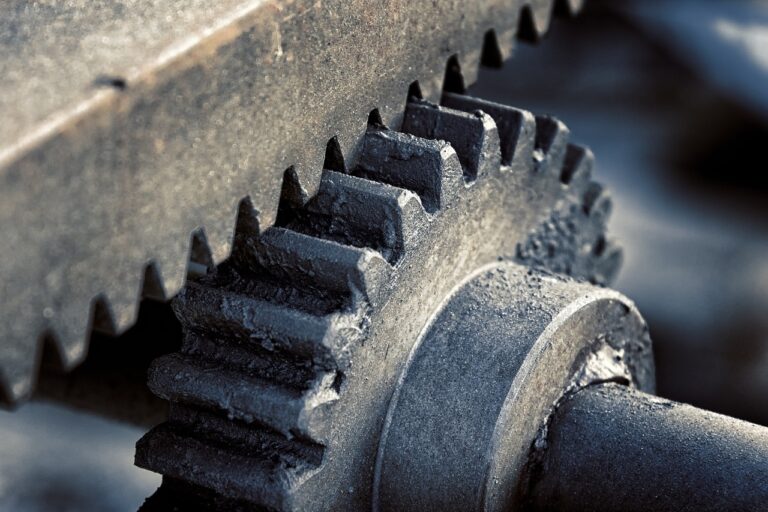
Rack and Pinion
This mechanism uses a small gear (pinion) meshing with a flat, toothed bar (rack) to convert rotational motion into linear motion.
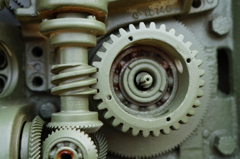
Worm Gear
A worm gear system consists of a screw-like gear (worm) that meshes with a helical gear (worm wheel). It provides high reduction ratios, minimal backlash, and self-locking capabilities, which prevent reverse motion.
Key Term
Reduction Ratio : The ratio obtained by dividing the number of teeth on the driven gear by the number of teeth on the driving gear. This ratio is inversely related to rotational speed—when it’s greater than 1, the driven gear rotates more slowly than the driving gear. When it’s less than 1, the driven gear instead rotates faster.
Backlash: The intentional clearance created between the teeth of two meshing gears. If the backlash is too large, it can cause increased noise and vibration, as well as noticeable play when the rotation is reversed or when movement changes direction. For this reason, backlash is generally kept as small as possible. However, if it is reduced too much, friction increases, which can accelerate tooth wear and shorten the overall lifespan of the gear.
Self-Locking: In spur gears, rotation can be transmitted from either side—the driving or the driven gear—without any issue. However, a worm gear is different. Because of the angle and shape of its teeth, it is generally designed to rotate only when driven from the worm side. This self‑locking characteristic makes worm gears useful for preventing reverse rotation and avoiding accidents.
3. WHY THE NUMBER OF GEAR TEETH MATTER
Gears are used to either accelerate or decelerate motion. The number of teeth on each gear determines the change in rotational speed.
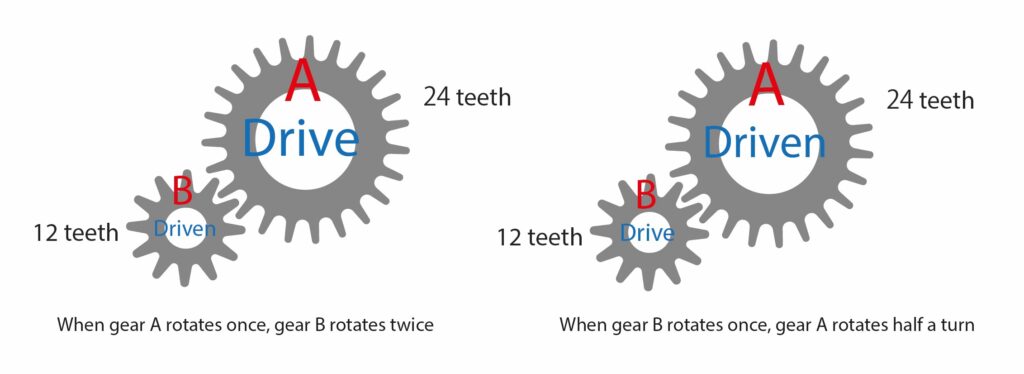
For example, a bicycle’s drivetrain uses this principle. A larger gear (with more teeth) requires less force but covers a shorter distance per pedal stroke. A smaller gear (with fewer teeth) requires more force but covers more distance with each turn.

4. HOW TO PRODUCE GEARS
The typical manufacturing process involves the following steps:
- 1. Rough machining to form the basic shape.
- 2. Hobbing to cut the teeth (gear cutting).
- 3. Perform hardening according to the required strength.
- 4. Perform grinding according to the required precision.
A hob is a tool (cutting tool) used for manufacturing gears and can be operated on dedicated machines such as hobbing machines or gear cutting machines. It can also be mounted on lathes or milling machines for processing. Hobbing is used to produce not only gears but also gear-like components, such as pulleys, splines, and serrations.
- Pulley・・・ A wheel for driving belts or chains.
- Spline・・・A shaft with grooves for transmitting torque.
- Serration・・・ A finer version of a spline, designed to reduce play between parts.
5. HOW TO MAKE GEAR TEETH
The teeth of gears are commonly produced using gear generation methods and gear forming methods, though various other techniques are also used.
Gear Generation
It is a method where a tool shaped like multiple thin, stacked gears is pressed against the gear, gradually cutting the entire surface. This is the most common method, known for its short processing time and high precision.
Gear Forming
It is a method where the gear teeth are cut one by one using tools like end mills designed for this purpose. While it is more difficult to achieve the same level of precision compared to the generation method, the advantage is that it can be done by simply changing the tool on machines you already own, without needing dedicated machines like hobbing machines.
Broaching
It is a method where a profile tool, called a broach, shaped to match the workpiece, is applied and pulled through in a single motion, transferring the tool’s shape. This method is mainly used for machining internal splines and is known for its short processing time and high precision.
Machining with Multitasking Machines
Multitasking machines can perform gear cutting using the gear generation method, such as hobbing, as well as gear forming using tools like end mills and slotters. They are also capable of gear skiving, a recently popular gear generation method.
Traditionally, gear cutting was primarily done using dedicated machines. However, due to the increasing demand for high-mix, low-volume production, process integration has advanced, and gear cutting is now frequently performed using multitasking machines that can handle multiple processes. These machines can perform turning and milling operations, and then proceed directly to gear cutting, all in one machine. This reduces work-in-progress and eliminates the precision loss caused by transferring parts between machines, resulting in more efficient production.
Key Term
Gear skiving: A method in which the workpiece and cutter are set at a crossing angle and rotated in synchronization based on the ratio between the number of teeth on the workpiece and the cutter. The cutter and workpiece make continuous contact while the tool feeds along the workpiece’s axial direction. This technique can be used for both internal and external gears, and it allows machining close to stepped or interfering areas with minimal clearance.
6. CONCLUSION
Gears have played a crucial role in industrial development and appear in symbols such as national flags, logos, and coins. Understanding the function and significance of different gear shapes is essential for those in manufacturing and mechanical engineering.
Recommended Whitepaper
Gear Machining on Multitasking Machines with Case Studies
Related Video
