
Estimated reading time: 6 minutes
CNC programming often sounds difficult at first because it involves many codes and strict rules. However, once you understand the basic principles, it becomes much easier to work with.
To keep things simple, it helps to start from the basics.
First, let’s take a look at what CNC programming is and how it works.
1. WHAT IS CNC PROGRAMMING?
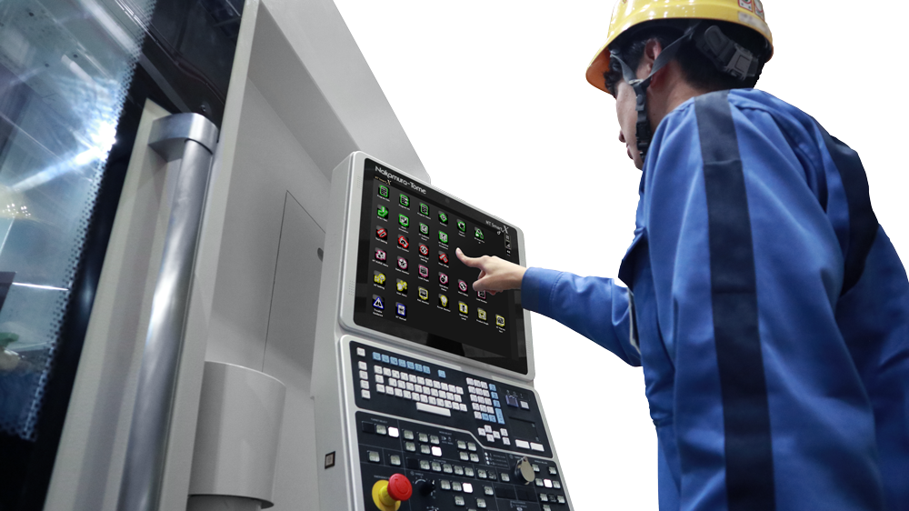
CNC stands for Computerized Numerical Control, which means controlling a machine using numerical values. A CNC machine tool operates based on numerical commands, and a CNC program describes how the machine should move and operate by using symbols and numbers under defined conditions.
Because an NC program lists many symbols according to specific rules, it may seem difficult to create or read without specialized knowledge.
However, once you understand the basic rules, NC programming is not as complicated as it first appears.
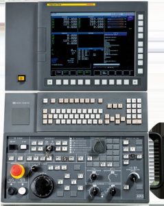
NC controllers come in several types and are generally divided into lathe systems and machining center systems. Each type has slight differences. Common controllers include FANUC, MELDAS, Yasnac, Siemens, and Heidenhain. The program structure depends on which NC controller the machine uses, so it is important to confirm this before programming.
In this article, we use CNC lathe programs with FANUC controls as examples and explain them in a clear and practical way.
2. G-CODE AND M-CODE
NC programs use symbols known as G-codes and M-codes. Basic codes are numbered from 0 to 99, although some machines use three-digit codes depending on their configuration.
Because G-codes and M-codes form the core of any NC program, this article explains their roles and introduces the most commonly used commands.
G-Code
G-codes are called preparatory functions. They are expressed as numbers following the G address and are mainly used for machining-related commands.
There are about 70 standard G-codes, ranging from G00 to G99. However, you do not need to use all of them. If you remember only the frequently used codes, you can create NC programs without difficulty.
The following section lists some of the most commonly used G-codes.
List of Commonly Used G-Codes
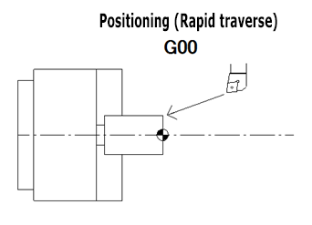
- G00 (Positioning (Rapid traverse))
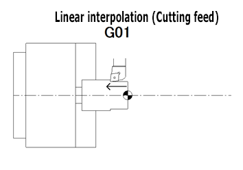
- G01 (Linear interpolation (Cutting feed))
- G02 (Circular interpolation CW)
- G03 (Circular interpolation CCW)
- G04 (Dwell)
- G28 (Automatic return to reference point)
- G40 (Tool nose radius compensation cancel)
- G41 (Tool nose radius compensation left)
- G42 (Tool nose radius compensation right)
- G50 (Coordinate system setting/Max. spindle speed setting)
- G54 (Workpiece coordinate system 1 selection)
- G92 (Thread cutting cycle)
- G96 (Constant surface speed control)
- G97 (Constant surface speed control cancel)
- G98 (Per minute feed)
- G99 (Per revolution feed)
There are about 70 G-codes in total. However, you only need to use around 16 of them for basic programming.
You can specify multiple G-codes in a single line as long as they belong to different groups. Some G-codes, known as canned cycles, simplify programming by combining multiple actions.
In this article, we focus only on the minimum set of G-codes needed to get started.
One-Shot G-Codes and Modal G-Codes
G-codes fall into two categories.
Some commands are effective only once when specified. These are called one-shot (non-modal) G-codes.
Other commands remain active until another code from the same group is specified. These are called modal G-codes.
You do not need to think too deeply about code groups.
For example, a machine cannot follow both “G00: rapid traverse” and “G01: cutting feed” at the same time.
Likewise, it cannot execute “G02: Circular interpolation CW (clockwise)” and “G03: Circular interpolation CCW (counter clockwise)” simultaneously.
Because these commands conflict with each other, they are assigned to the same group.
M-Code
M-codes are called auxiliary functions.
They are expressed as numbers following the M address and are mainly used to control machine operations.
For example, the command “rotate the spindle in the forward direction” is written as M03.
The command “turn on the cutting fluid” is written as M08.
Because M-codes control machine actions, machine builders define them rather than CNC controller manufacturers. For this reason, the assigned functions can differ depending on the machine builder. Even if two machines use FANUC controllers, the same M-code number may control different functions if the machines come from different builders.
There are about 80 standard M-codes, ranging from M00 to M99. However, as with G-codes, you do not need to use all of them. By learning only the commonly used M-codes, you can create NC programs effectively.
Below are examples of frequently used M-codes.
Since M-code functions vary by machine builder, the examples here are based on Nakamura‑Tome CNC lathes.
List of Commonly Used M-Codes
- M00 (Program stop)
- M01 (Optional stop)
- M03 (Spindle start (forward direction))
- M04 (Spindle start (reverse direction))
- M05 (Spindle stop)
- M08 (Coolant start (high pressure coolant)
- M09 (Coolant stop (low/high pressure coolant)
- M10 (Chuck close)
- M11 (Chuck open)
- M20 (Fixed air blow ON)
- M23 (Chamfering ON)
- M24 (Chamfering OFF)
- M30 (Memory mode operation reset & restart)
- M41 (Spindle selection (C-axis OFF))
- M86 (Spindle lock ON)
- M87 (Spindle lock OFF)
- M88 (Rotary tool spindle start (forward direction))
- M89 (Rotary tool spindle start (reverse direction))
- M90 (Rotary tool spindle stop)
- M91 (C-axis selection (C-axis connection))
- M98 (Sub-program call)
- M99 (End of sub program)
Although there are about 80 M-codes in total, you only need around 22 of them for basic programming.
As an important point, you can specify only one M-code per program line.
You cannot write multiple M-codes on the same line.
3. COORDINATE SYSTEM (MACHINE ORIGIN AND WORKPIECE ORIGIN)
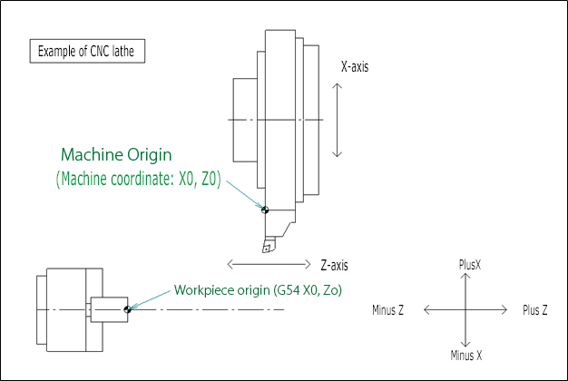
A CNC lathe uses two reference origin points.
One is the machine origin, which serves as the fixed reference point of the machine itself.
The other is the workpiece origin, which the programmer can freely define when creating an NC program.

One of the most important steps in NC programming is deciding where to set the workpiece origin.
In most cases, the workpiece origin is set at the point where the machined end face intersects with the spindle centerline. The position of the workpiece origin is expressed by the coordinates X0 and Z0.
For the X-axis, the geometry offset represents the distance from the cutting tool tip to the spindle centerline.
For the Z-axis, it is defined as the distance from the machine origin to the machined end face.
The tool then moves based on this workpiece origin. Because the machined end face is usually defined as Z0, cutting operations are performed in the negative Z-axis direction.
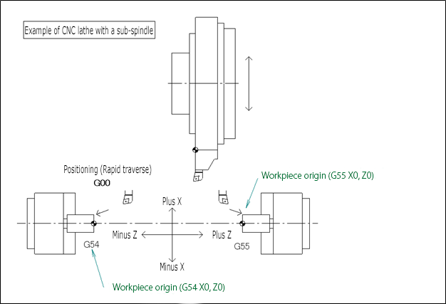
For machining on the sub-spindle, the second workpiece coordinate system, “G55 (Workpiece coordinate system 2 selection)”, is used. All coordinates are calculated based on this reference point. The positive and negative directions of the machine’s Z-axis follow the same basic definition as on the main spindle.
However, because a single tool-turret machines both the left and right spindles, the direction of cutting along the Z-axis is reversed. As a result, when machining on the sub-spindle, cutting operations are performed toward the positive Z-axis direction.
The positive and negative directions of the X-axis are the same for both the main spindle and the sub-spindle.
4. CONCLUSION
In this article, we explained G-codes, M-codes, and coordinate systems used in CNC lathe programming. Although G-codes and M-codes may appear numerous at first, you can see that the minimum set required for programming is actually quite limited.
G-codes control machining-related commands, while M-codes control machine operations.
By combining these codes correctly, you can perform precise and reliable machining when creating NC programs.
The workpiece origin is also a critical reference point in NC programming. It is a good practice to mark this point clearly on the drawing. If the workpiece origin changes, a CNC program that you carefully created can produce completely different results. A CNC program works correctly only when the programmer’s intent is accurately conveyed to the machine and to those responsible for setup and machining.
Related Video
Conversational NC Programming Software “Protona”
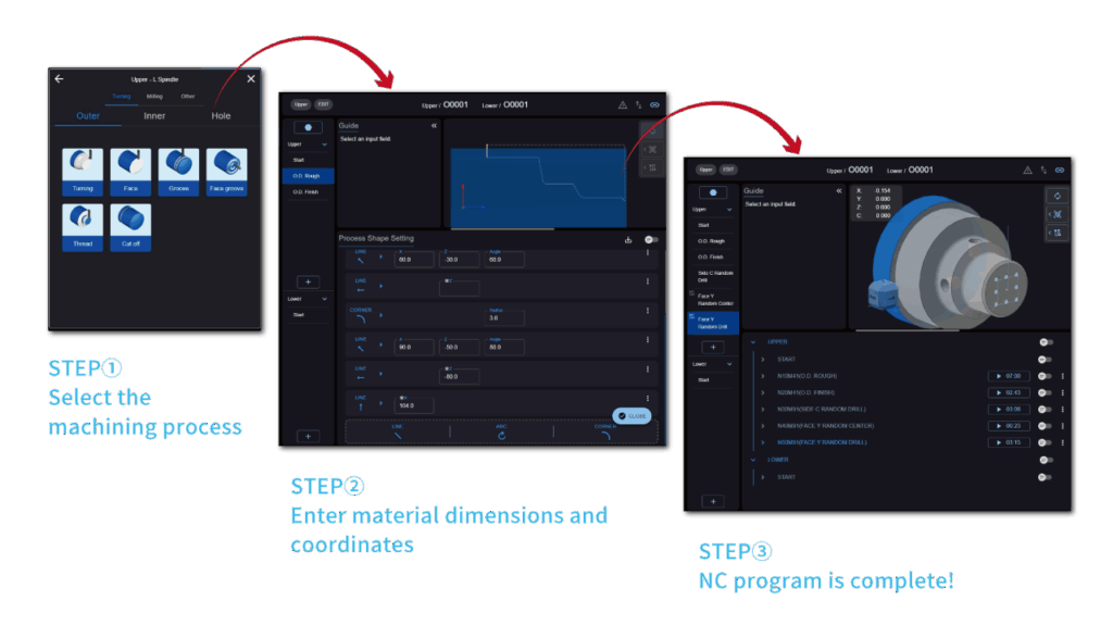
Protona offers a simpler and more intuitive user experience.
Even beginners can create professional-quality NC programs while keeping learning time to a minimum.
